Our simulation controller is specifically designed for building HIL (Hardware-in-the-Loop) systems, enabling advanced testing and validation of embedded software in electronic control units for complex systems. HIL testing reduces development time by simulating intricate scenarios that are challenging to reproduce in laboratory or field environments. With years of expertise in HIL system development and integration, we have crafted a versatile controller that meets the rigorous demands of various industries. Built on a reconfigurable industrial system, it features a real-time controller, FPGA, and modular connectivity for up to ten modules, ensuring minimal response delays and high-performance digital processing. Compatible with Kepstronic and third-party control modules (such as PXI series R modules), our solution delivers reliable, deterministic operation and supports both industry-specific and custom applications tailored to client requirements.
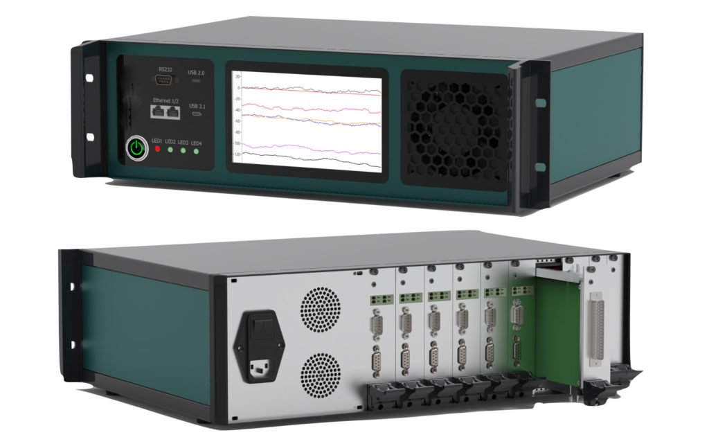
The RTC chassis is a case that can be either desktop or rack-mounted (19”). The chassis provides power and cooling for the controller and modules, and also contains a communication board. Modules installed in the chassis connect directly to the FPGA, without buses or intermediate elements, ensuring minimal control delays and maximum synchronization between modules.
The RTC controller consists of a processing system and programmable logic. The processing system operates under a real-time operating system, ensuring reliability and determinism for the tasks performed. The programmable logic facilitates interaction with the modules, as well as high-speed control and digital data processing.
Digital I/O module | RTC-D510 |
Number of DI channels | 8 |
Logic level high voltage | 5...24 V |
Logic level low voltage | 0...2 V |
Maximum frequency | 250 kHz |
Number of DO channels | 12 |
Type of output | dry contact |
Switched voltage | 1.5...33 V |
Maximum current | 6 A |
Maximum frequency | 4.5 kHz |
Analog Input Module | RTC-A301 | RTC-A302 |
Number of channels | 16 | 16 |
Measurement range | ± 10 V | ± 20 mA |
Connection scheme | non differential | non differential |
ADC resolution | 16 bit | 16 bit |
Type of ADC | SAR | SAR |
Sampling frequency (max) | 125 kHz | 125 kHz |
Input bandwidth (-3 dB) | 22.5 kHz | 22.5 kHz |
Resistance | 5 MΩ | 249 Ω |
Error | 0.2 % | 0.2 % |
Analog Output Module | RTC-A402 | RTC-A401 |
Number of channels | 16 | 16 |
Measurement range | ± 10 V | ± 30 V |
Connection scheme | non differential | non differential |
DAC resolution | 16 bit | 16 bit |
Type of DAC | SRS | SRS |
Sampling frequency (max) | 96 kHz | 96 kHz |
Error | 0.2 % | 0.2 % |
Thermal resistance simulation module | RTC-E120 |
Number of channels | 5 |
Connection scheme | 4-wire |
Resistance range | 30...250 Ω |
Types of simulated sensors | Pt100 |
Temperature setting step | 1 °C |
Error | 1 °C |
Thermocouple simulation module | RTC-E140 |
Number of channels | 16 |
Output range | ± 100 mV |
Connection scheme | non differential |
ADC resolution | 16 bit |
Type of ADC | SRS |
Sampling frequency (max) | 96 kHz |
Error | 0.2 % |
LVDT simulation module | RTC-E110 |
Number of channels | 4 |
Maximum amplitude of the reference signal | ± 10 V |
Maximum frequency of the reference signal | 10 kHz |
Maximum output signal amplitude | ± 10V |
Output signal sampling frequency | 120 kHz |
ARINC-429 Interface Module | RTC-P650 |
Number of receiving channels | 4 |
Number of transmission channels | 4 |
Transmission error | 12.5 kbit/s; 100 kbit/s |
RS-485 Interface Module | RTC-P610 |
Number of channels | 5 |
Connection scheme | 2-wire |
Baudrate (max) | 921600 |
Termination resistor | 120 Ω |
Protection offset resistors | 1.5 kΩ |
Sampling frequency (max) | 96 kHz |
This module provides wideband 2×2 receive and transmit paths from 70MHz to 6GHz range, making the device ideal for a broad range of fixed and mobile SDR applications.
The module combines the RF signal path and high-speed programmable logic.